You made the plunge into fuel injection and purchased one of The Dub Shop packaged kits! I’m not going to lie to you. This will take longer than installing a set of dual carbs but trust me… The results will be unbelievable!!! Soon you too will be saying “friends don’t let friends drive with carbs”. Read on; we’ve got some install tips for you. Always feel free to email or call with any additional questions or concerns. We love VW’s as much as you do and want you to be totally satisfied with your purchase.
Familiarizing yourself with the parts
Start with laying all the kit components out and familiarizing yourself with what everything is and where it will all go in the car. The garage floor or the kitchen table works well for this. If you have one of my complete wire harnesses, great! If not, it’s not too late as long as you don’t have a show to get to ;) Trust me, the harnesses are great quality and will make your install so much easier. Some of the items you will notice will be the ECU (electronic control unit) & relay board (optional) This is the heart of your system. All wires and one manifold vacuum reference will be run to this box. Use common sense when mounting this. While the MegaSquirt system is quite robust and can handle vibrations well, don’t mount the ECU where it can get wet or stepped on! Many bug owners opt to mount them on the driver’s side floor pan opposite the battery or in the rear package tray. Bus owners may choose under the rear seat, in a cabinet on camper models or anywhere else where there is ample room to mount and run wires to. Try a few different spots and think out how everything will run to the ECU before committing to a spot. Remember we (you, I and everyone else that admires your car) wants a clean install!

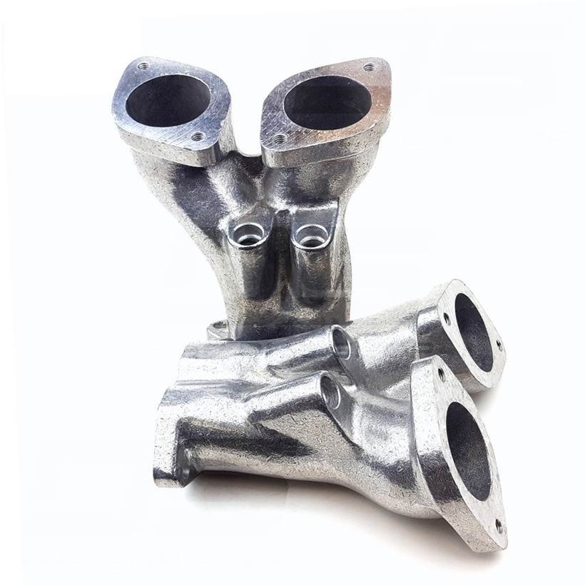
Intake System
Intake manifold, throttle body's & end castings; these will all install basically just like the factory intake manifold and end castings do on a stock 1600cc engine. Or dual carburetors on a performance engine. This is somewhat out of the realm of these instructions but we will provide some pointers.
If you have never removed or installed any intake components you may want to seek professional help or ask a knowledgeable peer. When preparing to install the fuel injectors into the end castings be sure to use some lubrication to not tear the o-rings on the injectors. A drop of oil from the dipstick works well. With the Mexican intake system you will notice the accelerator cable hooks up in the factory location. Use a barrel nut and your 8mm wrench to install. With a German plenum you will need to relocate your accelerator cable tube to left and down of the normal cable hole. Measurements can be provided if needed. Take your time; measure twice, drill once. Unless you already have a late model fuel injection shroud. Then the hole is already in place. Keep in mind you will be drilling close to the oil cooler so be careful! With dual throttle body's the install will vary based on your engine type and linkage chosen. You will also need to route your vacuum lines correctly. For a vacuum diagram details, click HERE.


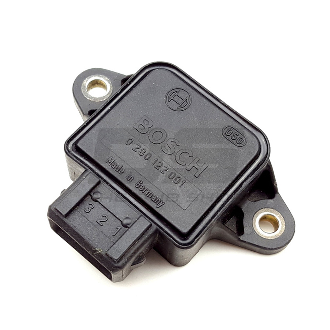
TPS sensor (Throttle position sensor)
The throttle position sensor is used to give ECU a pedal position with a 0-5volt signal. Depending on how fast or slow you press the pedal the ECU will interpret the data and decide whether or not to and add acceleration enrichment or enleanment. Think of this as the accelerator pump on a carb, If you slowly press the throttle you don't use any extra fuel and the transition is all done with the VE table. However, if you quickly depress the throttle the ECU will give extra fuel on top of the VE table to compensate for the fast transition with instant extra fuel the motor will need to rev quickly. If you are using Alpha-N instead of Speed Density, the TPS sensor now becomes the "load" amount instead the MAP sensor. But it also functions in the same manner for enrichments. The TPS will be mounted to the side of the intake manifold. Installation should be as simple as plugging it in.
MAP sensor (Manifold absolute pressure)
This sensor is on the ECU if you purchased an MS1, 2, or 3 and external if it is Microsquirt or MS3-Pro. It is used to give the ECU the engine load based on the vacuum or pressure in the intake manifold. Most single throttle body intake manifolds idle at a manifold pressure of 30-50 kpa. Dual throttle bodies depending on size and the engine combo can idle from 40-80 kpa. If you are cruising down the road on a flat surface there is generally no load on the engine and probably operating on the 40-50 kpa range. Full load at sea level is right around 101.4kpa. This would be WOT (Wide open throttle). On the lower end of the scale when you let off the throttle and engine brake, the load can drop as low as 15-20 kpa since the load of the engine is zero and the throttle plate(s) are closed. As an option, you can add a second MAP sensor for constant Barometric correction. With this second sensor, you can have great changes in altitude and the ECU will compensate the fuel required by taking fuel out while traveling up a hill and adding fuel as you go down hill.


MAT or IAT sensor (manifold air temp sensor)
This will be installed in the front of your throttle body (on Mexican setup) or in the plenum of the German kit. This will measure the actual temperature of the air going into your engine and provide critical data for the fueling algorithm and help with tuning. This sensor is 3/8”-18 NPT.
Colors - Orange and Black

CLT sensor (Coolant temp sensor)
The reason it is called a coolant temperature sensor is that it is actually a GM sensor for measuring coolant temp on a water cooled vehicle. Since our VW’s are air cooled we will be using it for our head temp sensor. This is the sensor that will tell the computer when the engine is cold and when to activate warmup enrichment's etc. It is the single Brass lug with a flying lead. I like to place this on the hot cylinder #3. The cylinder head tin bolt works great. NOTE: This is not an actual head temp sender. It will run approximately 50% less than actual head temp but will provide the temperature curve for hot and cold starts as well as the proper warmup enrichment's.
Colors - Yellow and Black

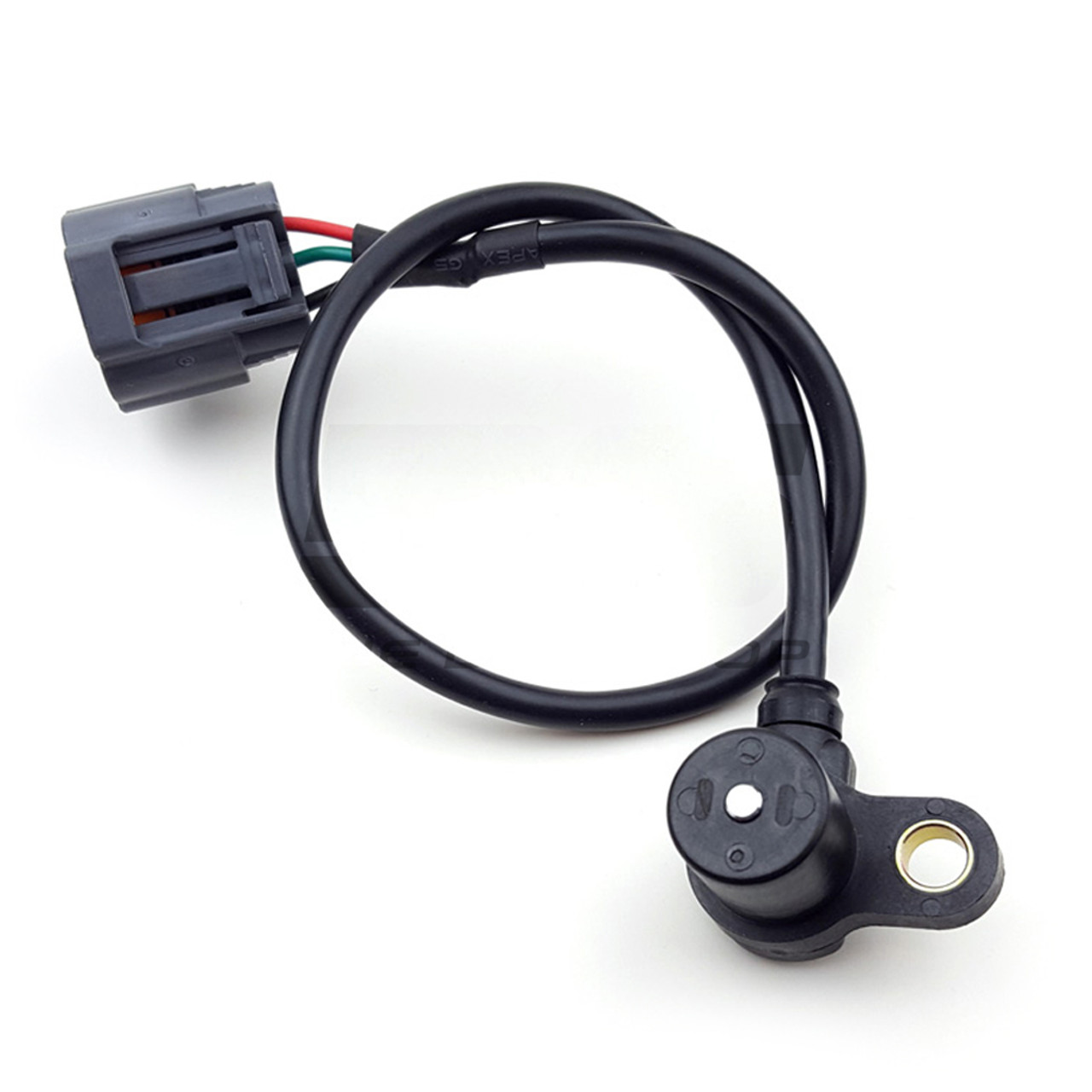
VR or Hall Sensors (Crank position sensor)
On a type 1 engine I am using a VR sensor (Variable reluctance), and for the type 4 engines I am using a Hall effect sensor (Square wave). These are used in conjunction with a toothed wheel placed on the crank somewhere, usually the pulley so the ECU can calculate the exact crank angle of the motor based on the missing tooth for very accurate ignition timing. I use a standard 36-1 trigger wheel on both engine types. For more information on installing your VR Sensor, Hall Sensor, or Trigger Wheel, you can find the detailed install page HERE.
Colors - Red, Green, Black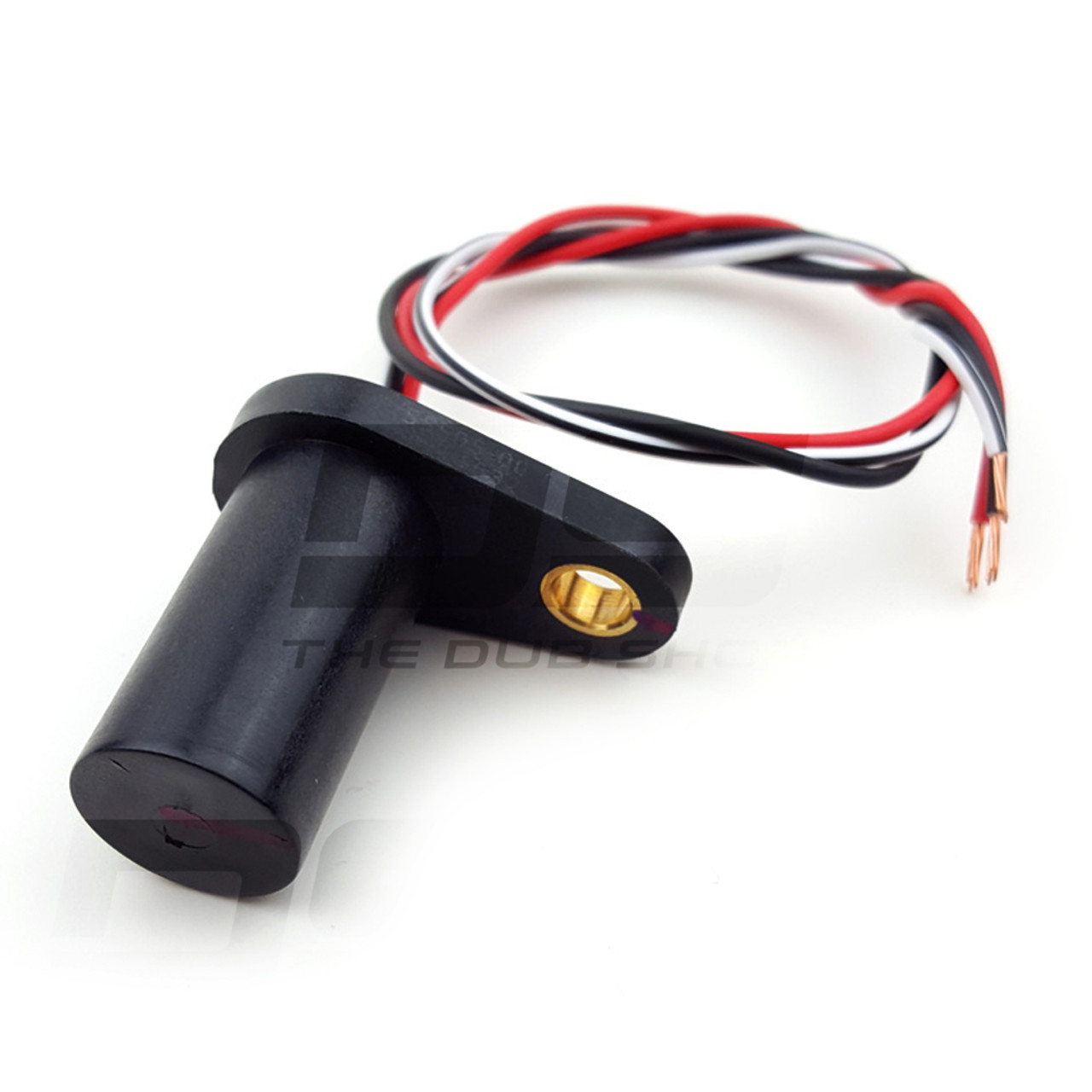

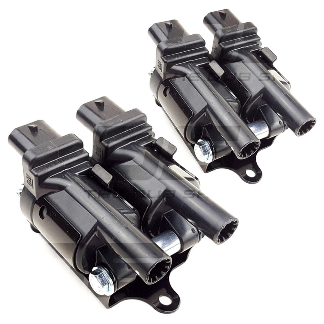
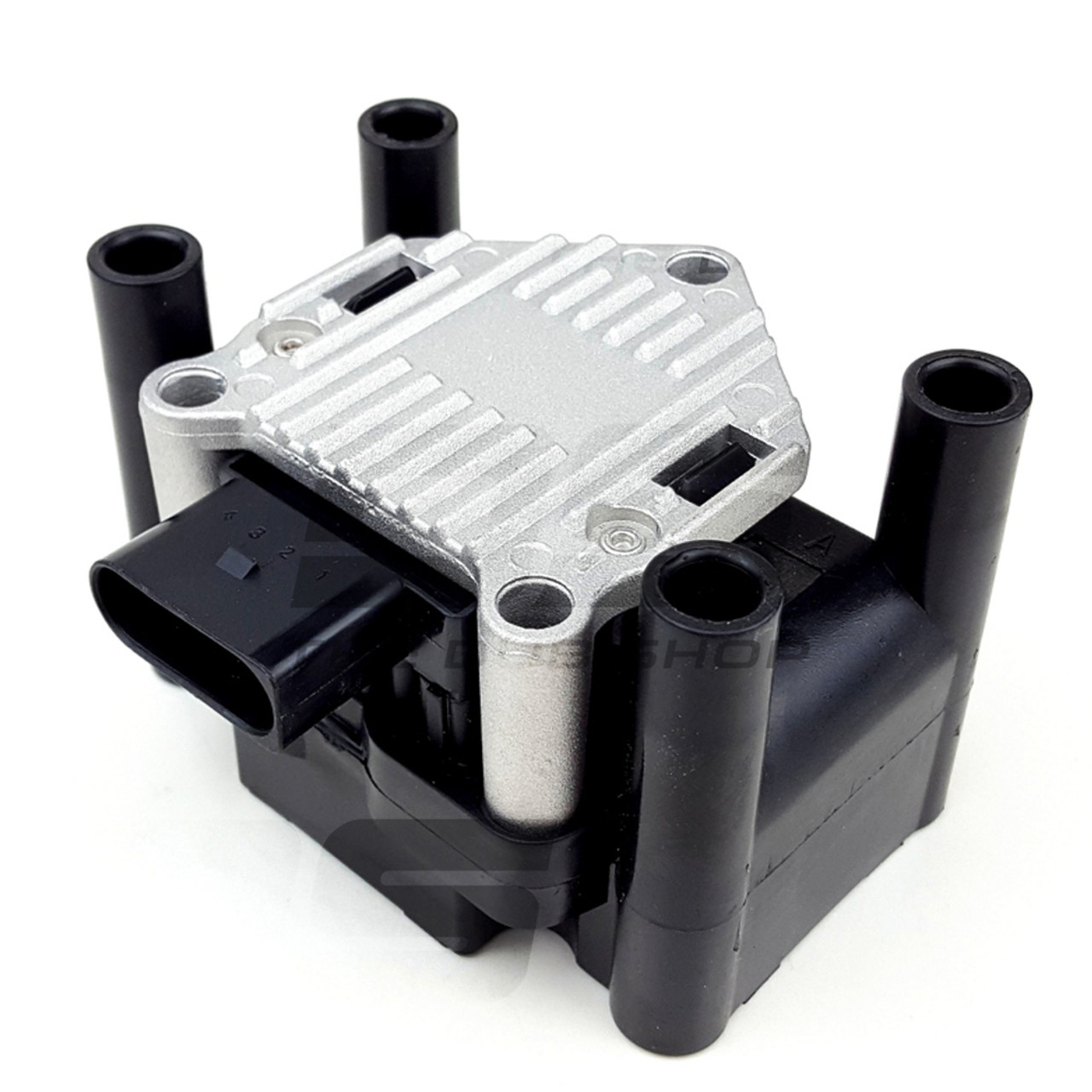
Ignition Coil(s)
There are many coil options but the most common being a single 4 post coil pack, the IGN-4. This coil fires 2 spark plugs at the same time. One cylinder is in it's compression stroke while the other is in the exhaust stroke. This is why it is named wasted spark. Don't be alarmed. It is still capable of powering engines well over 300hp. You can also choose to go with individual coil packs (COP or CNP). These can be run in the same fashion or upgraded to run sequentially.
The coil pack can be mounted on the shroud, behind the shroud, inside the car, pretty much anywhere you want it. The plug wires are universal length so you have some wiggle room. Once it is mounted you run the plug wires from the spark plugs to the coil pack and install the coil ends.
NOTE: When making the switch to EFI and ignition control you will also need to change your spark plugs. They need to be changed out for a resistor core type plug. So just get your favorite brand but pick the part number that has an R in it. In most cases, the gap can be started at .035" for NA and .032" for turbo up to 10psi or so at which point you may get misfires from the added fuel and compression. If this is the case start dropping the gap about .002" at a time until the misfire recedes.
For more information regarding ignition coils, click HERE.

Tank “T” Fitting
This will be used to take the one fuel line outlet on your tank and turn it into 2. This is provided with one 3/8" fitting for the filter feed and one 5/16" fitting for the fuel return from the factory fuel line. You will need to remove your gas tank for this and then remove the original fuel line outlet and filter sock that is used in the tank.

Fuel Pump, Filter, Pressure Regulator and 5/16" hardline
Ok, now onto plumbing the fuel system. Under the gas tank mounted to the pan opposite of the master cylinder is a great spot to mount the fuel pump and filter on a beetle. Buses can utilize the ample room under the gas tank or frame rails. The included 9mm fuel hose will attach to the 3/8” barb off of the fuel tank “t” and go into the fuel filter. Out of the fuel filter will be the same 9mm fuel hose to the fuel pump inlet. Out of the fuel pump will drop down to the supplied 7mm fuel hose. From the fuel pump outlet, you will go to the 5/16” hard line that runs to the back of the car. Now at the back of the car, you will go from the 5/16” hard line to one of the fuel rails on the engine. From that fuel rail, you will use the other barb on that rail to jumper over a piece of 7mm fuel hose to the other fuel rail on the opposite side of the engine. Out of that fuel rail, you go to the fuel pressure regulator inlet (see diagram below). Then out of the fuel pressure regulator, you go to your factory fuel line for your fuel return. Back at the front of the car, you will run a hose from the factory fuel line coming out of the tunnel up to the other side of the brass fuel tank “t” you previously installed at the bottom of your fuel tank. It should go without saying that you need to use the provided hose clamps at every joint as 43.5psi of fuel pressure will spray quite far if not tight! By the way, the Bosch fuel pressure regulator is rated for 43.5psi so you will basically screw the screw on top all the way in. If you have a vacuum referenced unit that will need a manifold vacuum signal as well. Whew, that was a lot. For more install information on the fuel system, visit the fuel system page HERE.
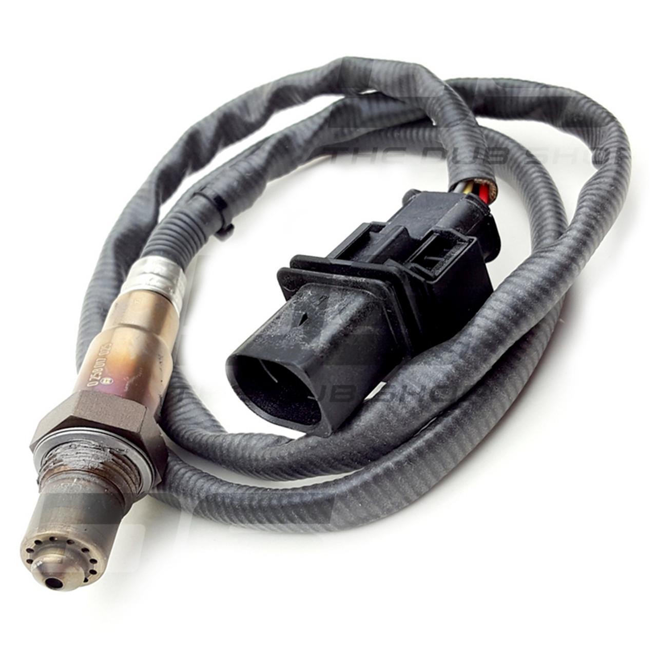
O2 Sensor
The O2 Sensor needs a bung welded into the exhaust. Make sure to account for the size of the sensor and the routing of its wiring when choosing a location to mount it.

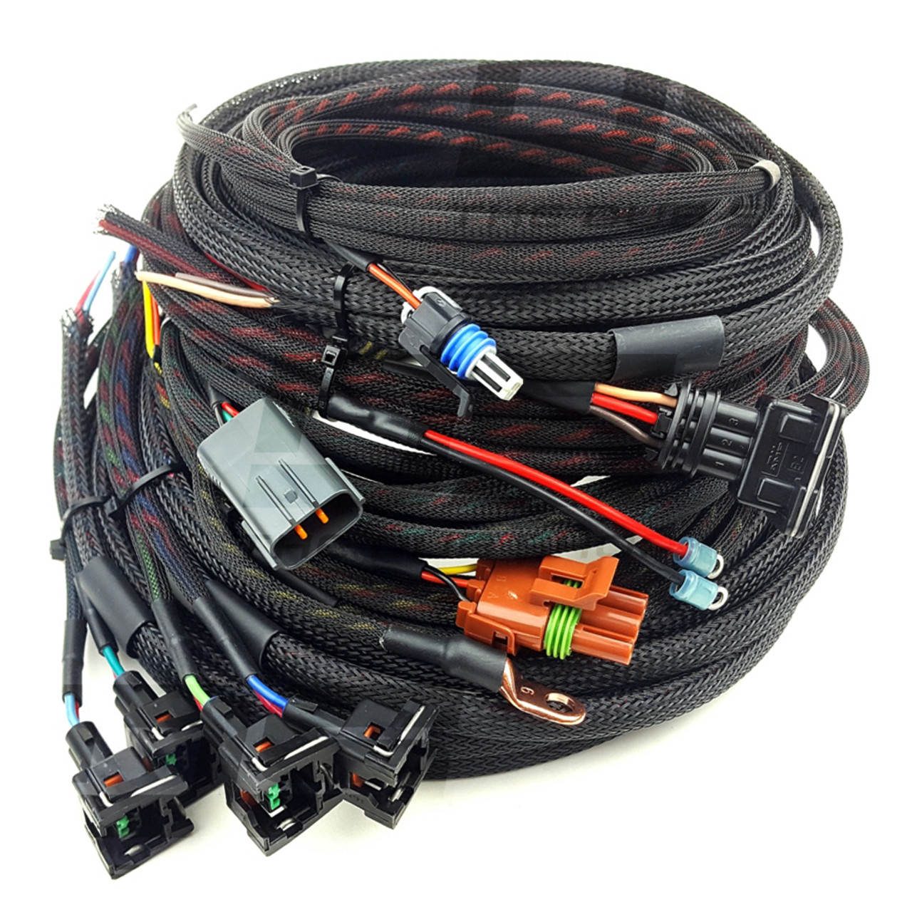
Wiring
Here comes the fun part. Well, it is at least for me, I love wiring. Take your time and plan out how to route all the wires cleanly. This is what everyone sees so take pride in your work and make it look good! There will be one of two diagrams you will use to wire up your system depending on whether you purchased a custom wiring harness or if you are just using the factory ms pigtail. The ms pigtail is fully labeled and this is the diagram you will use. For detailed information on wiring the car, visit the wiring page located HERE.

First Start
At this point you should be done installing the kit on the car. It is now time to connect to the ECU, test to make sure there are no problems, and start the car! Make sure to head to the First Start Page for detailed instructions on this procedure!