| Hardware Install | Sensor Wiring |
Software Setup |
Hardware Install
This package is available with a VR magnetic sensor and a Hall effect sensor (same dimension as a Honeywell GT101) to be the most universal.
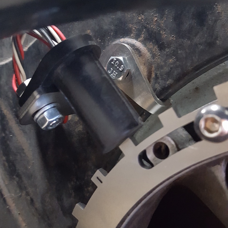
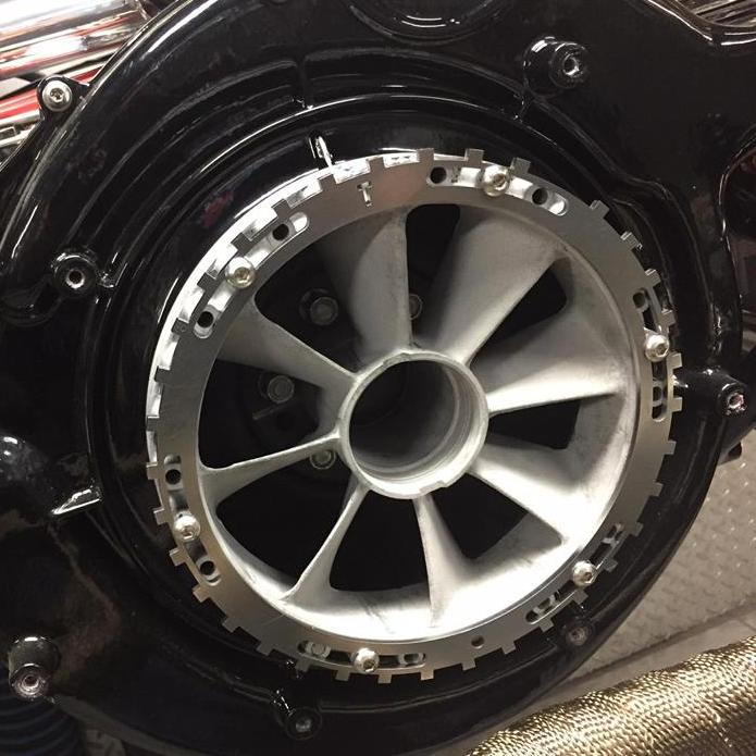
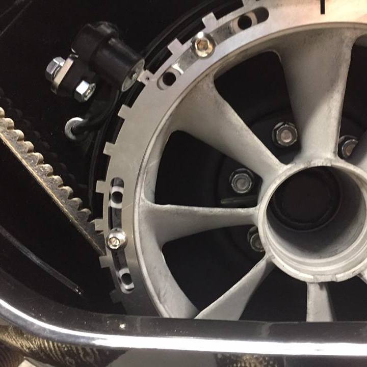
The Type 3 crank trigger will sit on top of the factory pre fan. The trigger wheel features 6 slots in which you will need to pick a symmetrical bolt pattern on the fan that does not have a counterweight in one of the holes. You will have 3 pattern options. These slots also provide the adjustment necessary to line up the sensor once mounted. After you have chosen a suitable set of holes you will nee to tap them with a 1/4" - 20 Tap and mount the trigger wheel with the provided Stainless socket cap machine screws. Keep it loose at this point.
The trigger wheel has a "T" at the top to indicate TDC. There is a small pin hole in the 9th hole counter-clockwise from the missing tooth. This is the sensor alignment tooth. Finally, there is a larger hole opposite the "T" to indicate BDC. With the engine at TDC, rotate the trigger wheel to center the sensor over the alignment tooth. Once that is done you can set the sensor clearance. VR sensors need .030-.040", Hall sensors can be .030-.060". At this point recheck sensor alignment and tighten all mounting bolts.
Hall sensor users only - You can test your sensor output at this time. Power the sensor with 12v to Red and ground the Black wire. Ground the negative lead of your multimeter or low current test light and probe the White/Black wire with positive lead. When the sensor is over a tooth the voltage should be under .25 volts, with the sensor in a gap the voltage will be at the supply voltage or 12v.
 |
 |
 |
 |
 |
 |
 |
 |
Sensor Wiring
Standard Sensor Wiring:
Red - 5v or 12v
Black - Sensor Ground
White/Black - Sensor Output
Software Setup
For Megasquirt 2/3 installations use these base ignition settings:
#1 Tooth Angle 80°
VR - Rising Edge
Hall - Falling Edge
Once the installation is complete you will want to verify timing with a timing light. If the computer readout does not match the timing light adjust the #1 tooth angle to get the two to match. This is very important.