Electronics
The ECU (Electronic Control Unit)
 |
With the large variety of ECU's available ECU's today, I have chosen the MS2 v3.57 (MS2 v3 pre 2016) to be my workhorses. They offer a perfect balance of features and functions for one getting started with EFI. There are other less configurable options (Microsquirt) and there are higher end models (MS3PRO) that will have you learning menus for hours and that is great for a 10s turbo street car, but if you have a 1776 and are just now starting to hate your carb you will soon be so happy! |
Relay Board
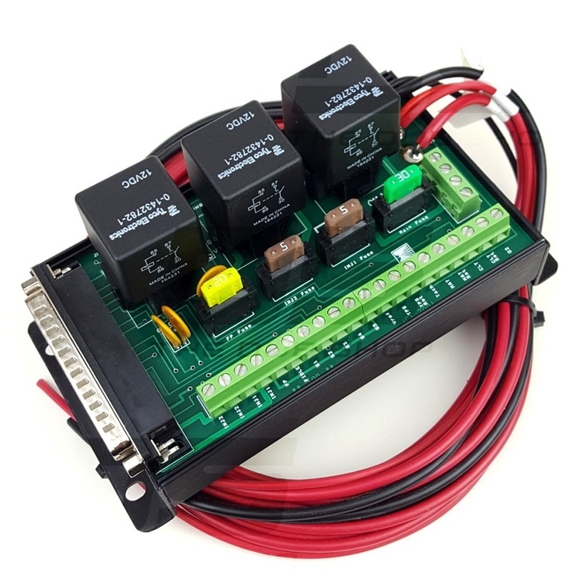 |
This is the relay board and I normally use this with the MS2 and MS3s ECU's and it is not compatible with the Microsquirt. For the first time installers this makes life SO easy. With most of my EFI packages I provide a pre terminated harnesses that relieves you of any harness building. Once all the sensors are plugged in you only have to run the wires to this relay board, trim the wires to length and screw them into the labeled terminal strip. I also have wiring diagrams to make it even easier. You can find those here. |
Relay Cable
 |
The relay cable ties the ECU to the Relay board and not needed if you choose to go with a Microsquirt. |
Complete Wire Harness
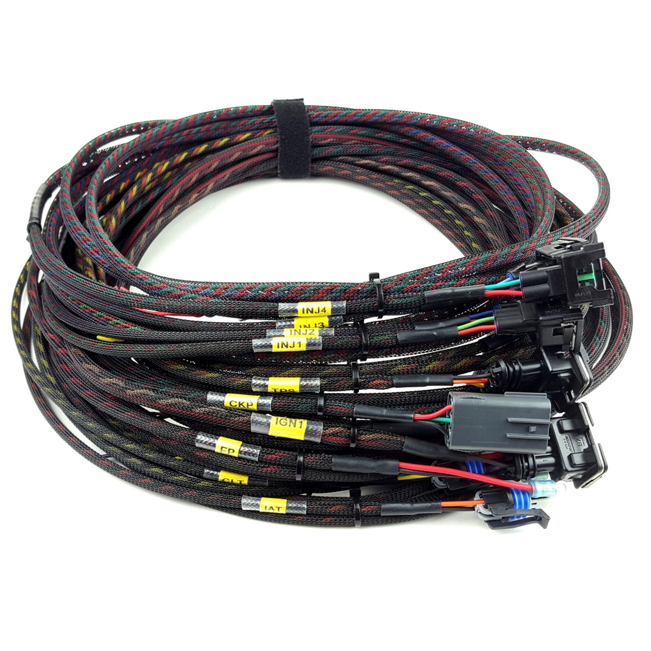 |
Here is an example of our terminated wire harness sent out with most complete EFI packages. This one has optional labels on each sensor for ease of installation. All the legs of our harness are twisted for added noise rejection to keep the wires flexible during install. All wires are covered in expandable sleeve with wire that is rated for engine bay temperatures. I also offer starter wire kits for those what to DIY or just need wire to get started. I can then provide all the connectors necessary as well. |
Sensors
Intake Air Temp Sensor (IAT)
 |
This reads the temperature of the air coming into the engine so that the amount of fuel can be adjusted accordingly. In NA installs, this can go before the throttle body or in the air filter housing. In turbo applications, make sure this is mounted after the turbo and anything that will modify temperature (Intercooler, Water/Meth injection). This should also be after the throttle body in single throttle body applications. |
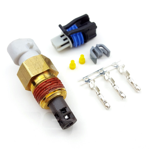
Modified Coolant Temp Sensor (CLT)
 |
This sensor reads the temperature of the engine. It uses a factory GM sensor base calibration and is modified to read surface temp of your head. It is not a replacement for a proper head temp sensor placed under a spark plug and shouldn't be used as such. I often get asked why I don't use oil temperature. Oil heats much slower than a head and cools much slower as well. This can lead to hard starting issues and you don't need to modify your engine case or add any fittings into your oil circuit. Win, win and win. |
Throttle Position Sensor (TPS)
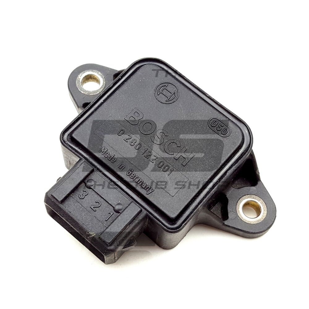 |
The TPS sensor is responsible for providing throttle angle data to the ECU. These run on 5 volts and usually operate in a range from .5v to 4.5v. Once open and closed throttle positions have been calibrated in the ECU this voltage is converted into a percentage between 0 and 100% and is displayed in the tuning software. In some naturally aspirated engines with large cams the TPS sensor is used as the main load parameter known as Alpha-N fueling. |
Manifold Pressure Sensor (MAP)
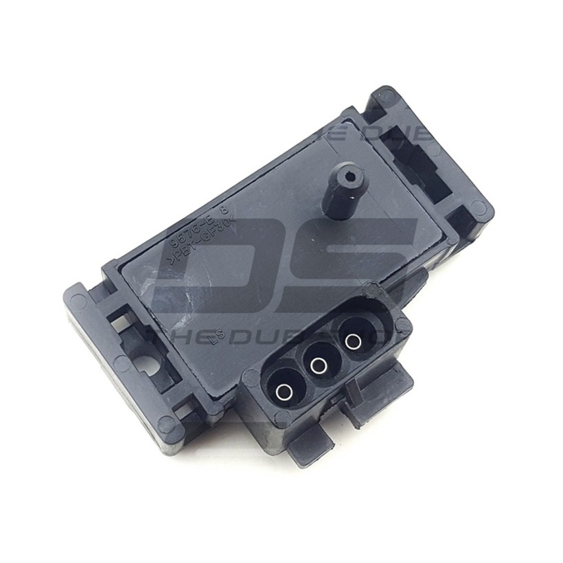 |
If you choose a Microsquirt ECU an external MAP sensor is needed. With the MS2 and MS3 this is included in the case. MAP is used to provide engine load information in the form of vacuum signal to the ECU. It requires a vacuum reference from a port after the throttle plates. This fuel control method is known as SD or Speed Density and also uses intake temperature to calculate the fuel needed. |
Fuel System
Fuel Injection Pump
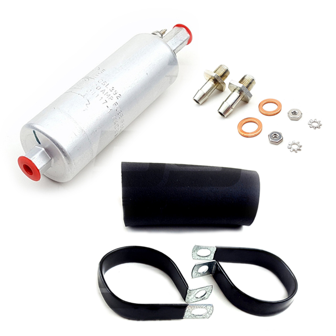 |
I prefer the Walbro inline fuel pumps for my packages. They can be used with a large variety of fuel fittings such as the 8mm nipples I use as standard, 06AN, 08AN, Banjo and the list goes on. These fuel pumps can handle all but the most crazy of engines supporting over 400hp with ease naturally aspirated or boosted. |
Fuel Filter
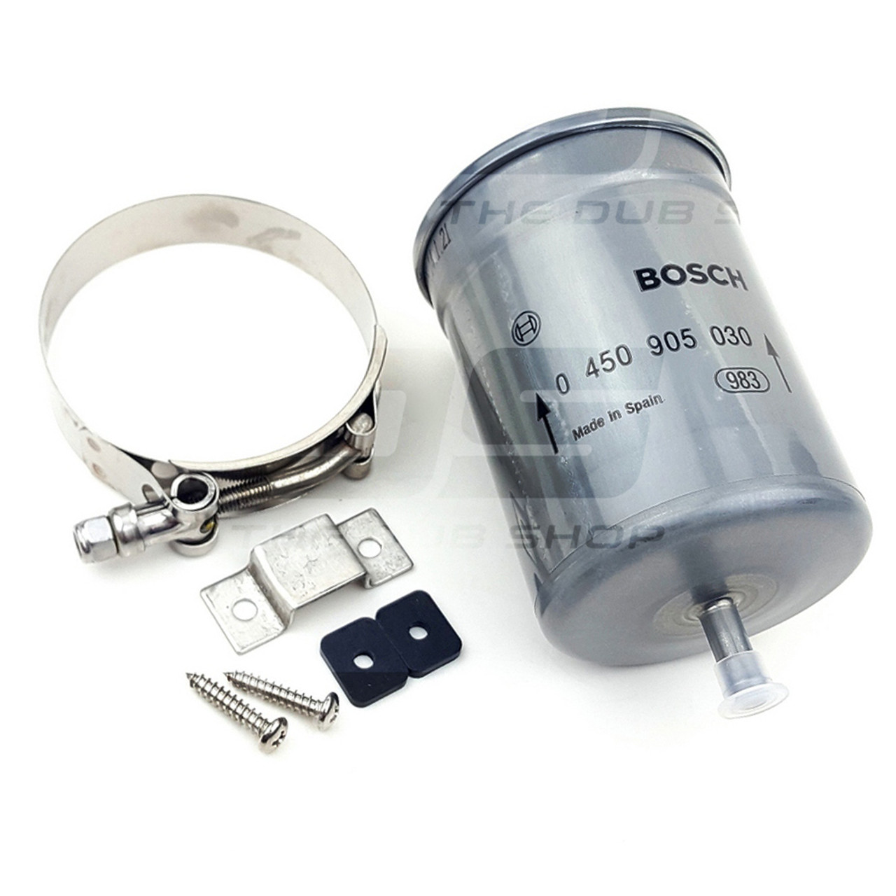 |
The fuel filter and is a major component in the fuel system. Without this debris can make it's way into your fuel pump or even your injectors causing premature part failure. I use larger Bosch fuel filter in my packages to provide OEM level protection and long service intervals. I would recommend adding this to your maintenance schedule about every 4th oil change.
|
Fuel Tank Tee
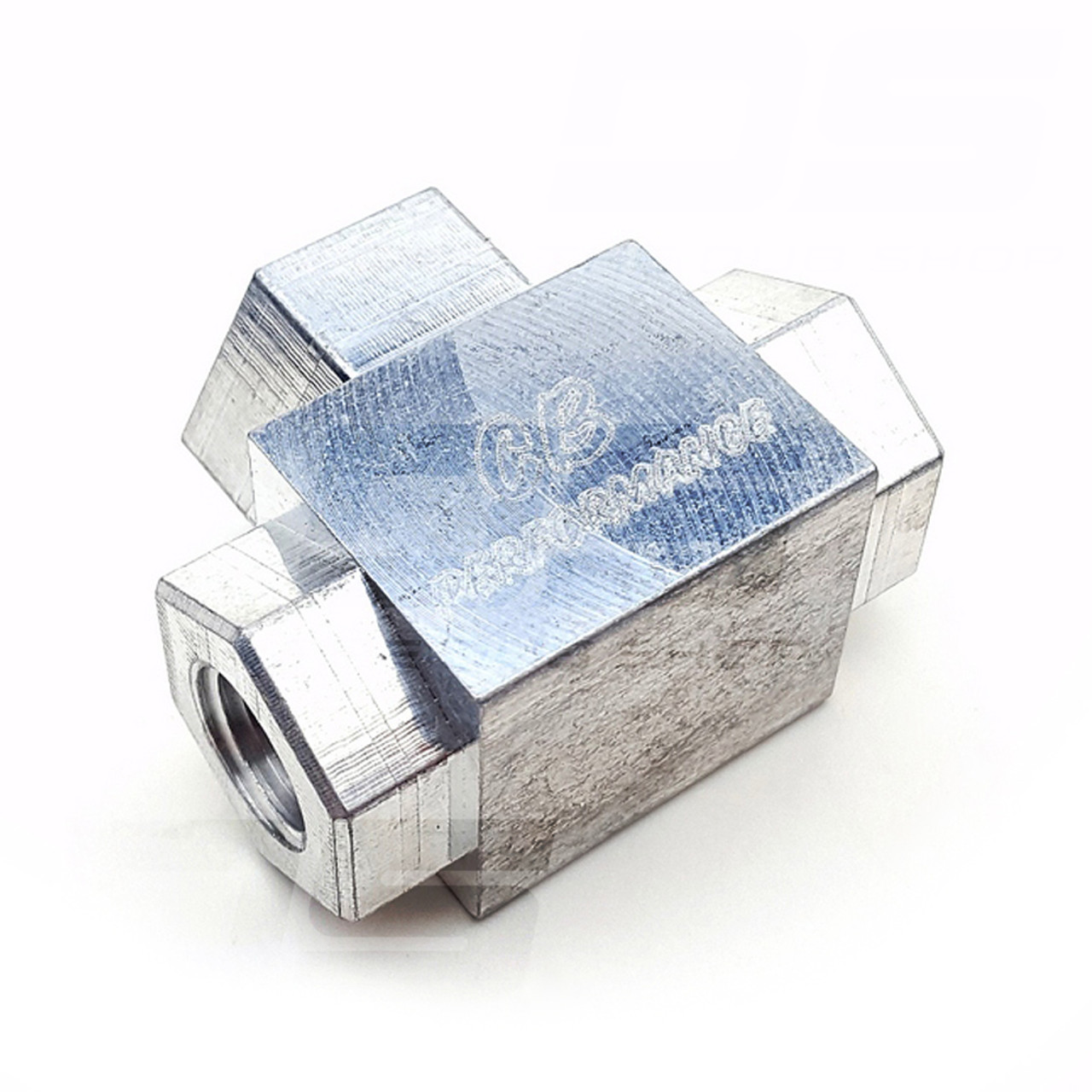 |
This fitting attaches to the fuel tank outlet. One side goes to the filter, feeding the fuel system. The other side is the return line. |
Fuel Hard Lines
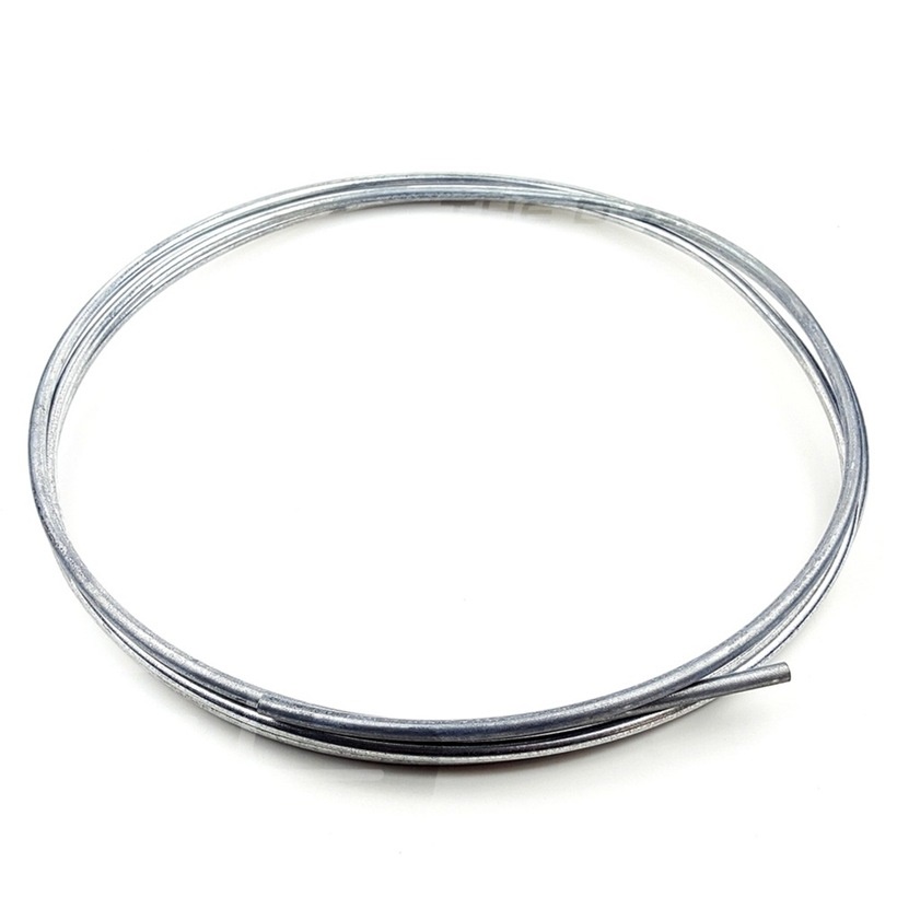 |
Hard lines is usually used to transport the fuel from one end of the vehicle to the other. This can run the length of your car and allow you to use the least amount of soft fuel hose. |
Fuel Rails
 |
Fuel rails are what will be used to to get the fuel into your injectors from the hose or hardline. These fit many brass or AN fittings depending on your application. |
Fuel Injectors
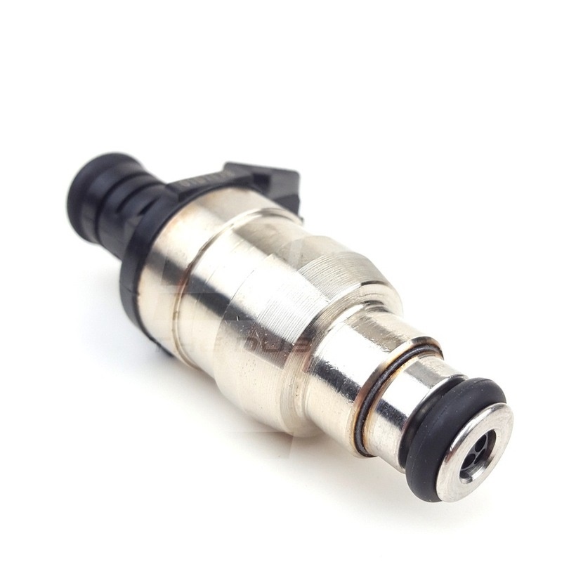 |
As the name states, these are used to inject fuel into the engine. These are replacing your old carburetor and are controlled from the ECU with a PW (pulse width). This allows for precise amount of fuel to be injected as needed. Once this fuel is burned your wideband 02 sensor is used to sniff the burned fuel mixture. This allows a closed loop control to take place (EGO correction) were the ECU can make small changes to the fueling and compensates for changing conditions. |
Fuel Pressure Regulator
 |
There are many fuel pressure regulators on the market. I've chose to make my own regulator body that uses Bosch type interchangeable regulators common on many modern cars. These range in static pressures from 2.5-5bar (36.25-72psi). I I offer the 3bar as standard. In high HP applications it may be beneficial to run a higher base pressure depending on the injectors being used. |
Ignition System
Crank Trigger Pulley
 |
One of the most important aspects of fuel injection is the ignition system. To provide a solid base for this a crank trigger pulley offers superior crank position resolution to the ECU in degrees. The most common being a 36 toothed trigger wheel with one missing tooth, or 36-1. This provides a good resolution from idle speeds to over 10,000 rpms. With a tooth every 10 crank degrees you can see how beneficial this is over a distributor based trigger with one tooth every 180 crank degrees. A crank trigger is needed for wasted spark application. I have the largest assortment of trigger wheels for air cooled cars on the market. You can find them all here. |
Cam Position Sensor
 |
My Mini Cam Sync is only needed when moving from wasted spark and bank fueling to sequential fuel, sequential spark or sequential fuel and spark. This sensor provides one sync pule to the ECU just before #1 top dead center on the compression stroke. This happen before the missing tooth on the crank passes the crank sensor. Once the pulse from the cam sync is received and then the missing crank tooth is seen the ECU knows to start the sequential cycle over firing each injector or plug in the firing order starting with cylinder #1. A link to the cam sensor page can be found HERE. |
Ignition Coil - IGN4
 |
The IGN4 is a powerful wasted spark coil and uses common HEI spark plug terminals. This is my goto wasted spark coil with MS2 applications. The coil fires cylinder pairs 1+3 and 2+4 together. Having a single 4 post coil eliminates the moving parts of a distributor as well as eliminates cylinder cross-firing in a distributor cap. For more information ignition coils and how they differ check out my ignition coil tech page found HERE. |
Induction
Throttle Bodies
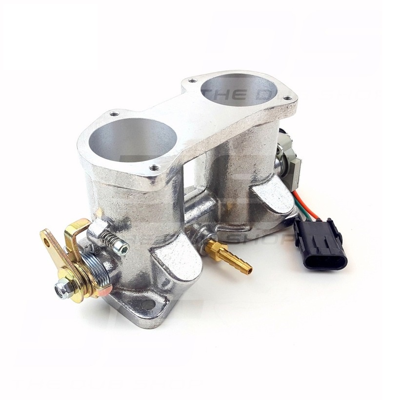 |
Throttle bodies can either be drilled for injectors or not, depending on which intake manifold you are using. |
Intake Manifolds
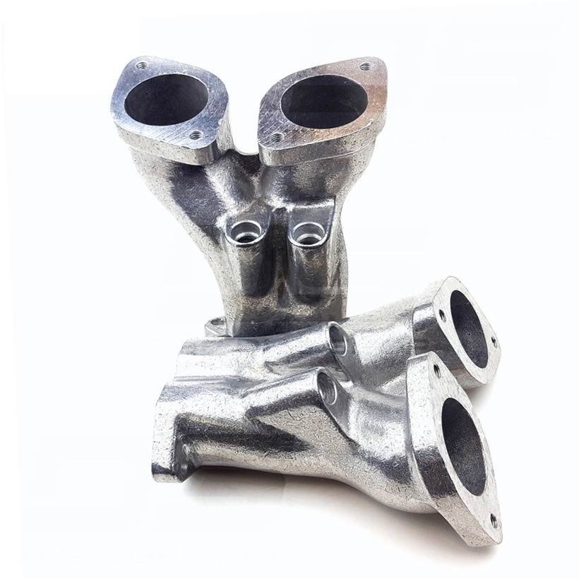 |
These are the intake manifolds. If your throttle bodies are not drilled for injectors then your intake manifolds must be. The ones pictured are drilled. |
Vacuum Lines
 |
Vacuum lines must be run from a throttle body or other vacuum reference location the MAP sensor either in the MegaSquirt unit (2/3) or to the separate MAP sensor (Micro/Pro). If you are looking for a typical vacuum routing diagram, you can find that HERE. |